A thread is a simple and cost-effective way of mating two parts. They efficiently fasten two parts together to ensure stability, functionality, and performance.
CNC machining is a subtractive manufacturing method that can be used to make all sizes of internal and external threads.
To achieve your desired result, you must get all the details right in the design of your thread. In this post, I’ll explore in detail how to select and specify threads for CNC machining as well as draw your attention to key design considerations. I’ll also take you through how we at Penta machine threads to give you more background for your design.
Internal vs external threads
Firstly, it’s important to know the distinction between internal and external threads.
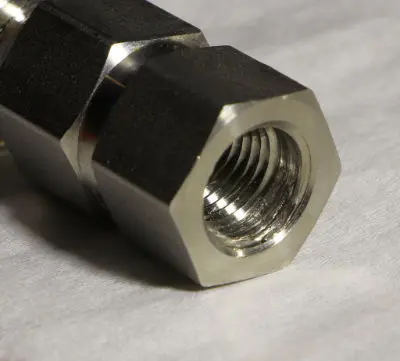
An internal thread is also known as the female part. This is what you’ll often see inside a component and where a screw or bolt will be threaded to mate two components.
An external thread, or the male part, is more likely to be the screw or bolt but not always.
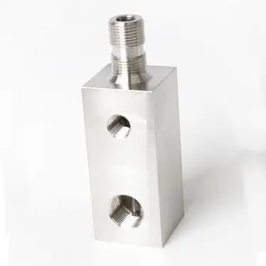
These examples clearly show the difference between an external thread and an internal thread.
| External thread | Internal thread |
|---|---|
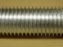 |  |
|
| Plbcr, CC BY-SA 3.0 , via Wikimedia Commons |
Both internal and external threads can be CNC machined.
It’s vital to recognise the difference between internal and external threads and always ensure they are clearly marked on technical drawings to avoid any confusion.
How are threads CNC machined?
Here at Penta, there are several ways we would machine a thread which I will outline here for your background information.
Tapping
Tapping is carried out on a CNC milling machine. A tap is where we initially drill a hole to the core diameter and then use a tap, essentially using the male part of the thread to cut the female part of the thread. This creates a threaded hole.
There are two different types of thread:
- Formed/roll tap – this creates a stronger thread as the material is formed, swaging, or pushing the material away. You therefore don’t get any waste material. When roll tapping, the drill diameter is slightly different because it pushes the material away.
- Cut tap – this is where the material is cut away and it does produce waste material. The tap here is the exact diameter needed.
There are two main types of machine taps:
- Spiral point – used for through holes and pushes the material out of the hole.
- Spiral flute – used for a blind hole (i.e. doesn’t go through) and enables the waste material to be removed from the hole as it’s machined.
The drawback of milling and tapping is that there is a chance of the tap breaking and the part being unsalvageable. The benefit is that it’s a quick and efficient method of creating a thread.
Thread milling
With this method, we still drill a hole at core size on a CNC milling machine. Then we use a tool called a thread mill to interpolate the thread into the hole.
We are more likely to use this method on a harder material such as stainless steel or titanium or occasionally in a softer material on a component where we couldn’t risk a tap breaking and ruining the part. Thread milling is also a slower process than tapping.
When deciding which method to use, we would weigh up all the factors including how many threads need to be milled, the hardness of the material, the value of the part, and production timelines.
Thread turning
This is where we create the thread using a thread-turning tip on a lathe. It can be used to create internal and external threads although external threads are more common on CNC turned components.
The tool used for this is generally the pitch of the tip. The part is spun on the lathe and the tool runs up and down the length of the shaft which is what creates the helical thread.
Not getting what you want from your CNC machining supplier?

Specifying threads
The great thing about threads these days is that they have become standardised. This has made life simpler for us designers and engineers but there are still important considerations to be taken into account when designing a thread for CNC machining.
There are certain parameters you must include in your drawing…
Thread standards and series
Thread standards and series play a pivotal role in CNC machining, offering a standardised framework for designing, manufacturing, and using threaded components across various industries.
These standards ensure the compatibility and interchangeability of threaded parts, providing consistency and reliability in engineering and manufacturing processes.
Thread standards
The standard of a thread is the combination of diameter and pitch. There are two main series, the Unified Screw Thread (in inches) and the Metric Thread Standard (in millimetres). There are two types of thread for each series – fine thread and coarse thread.
UN (Unified Thread Series)
Dimensions for the UN series are specified as a fraction of an inch. It has standardised pitch and thread angles, making it a common choice for various applications.
UN series includes the following types:
- UNC (coarse pitch)
- UNF (fine pitch)
- UNEF (extra fine pitch)
- UNJC
- UNJF
Metric (M)
This series is governed by ISO (International Organization for Standardization) and is prevalent globally. It simplifies thread design by using the millimetre as the base unit and adhering to standardised thread pitches and angles.
Metric threads are known for their precision and are widely used in many industries in the UK.
Metric series includes the following types:
- M
- MJ
Both the UN and M series are used widely in the UK. Here at Penta, we see about 80% metric vs 20% UN. It does tend to be very industry-specific so it’s worth you checking what is standard for your industry.
Other types of thread:
- Pipe threads: NPT, NPS, NPTF
- Multi-start threads
- British Standard Pipe: BPT, BPTT, BSP, BSPT, BSPP
- British Standard Whitworth (BSW)
- British Standard Fine (BSF)
Thread series
There are four primary thread series:
- Coarse Thread Series: featuring a lower number of threads per inch, making them relatively larger and more robust. Preferred for applications where strength and rapid assembly are essential such as construction.
- Fine Thread Series: featuring a higher number of threads per inch, resulting in smaller and more closely spaced threads. They excel in applications demanding precision and finer adjustments, often found in aerospace, electronics, and instruments.
- Extra Fine Thread Series: goes a step further than fine with an even higher thread count per inch. Typically used in specialised applications requiring exceptional accuracy such as optical instruments and laboratory equipment.
- Pipe Thread Series: specifically designed for pipe fittings and sealing in fluid-carrying systems. They come in various standards, including NPT and BSP, each with unique features to cater to different needs.
Anatomy of a thread
The following diagram shows the factors of a thread that must be specified when designing threaded components. This will ensure that the two mating threads fit together securely and without issue.
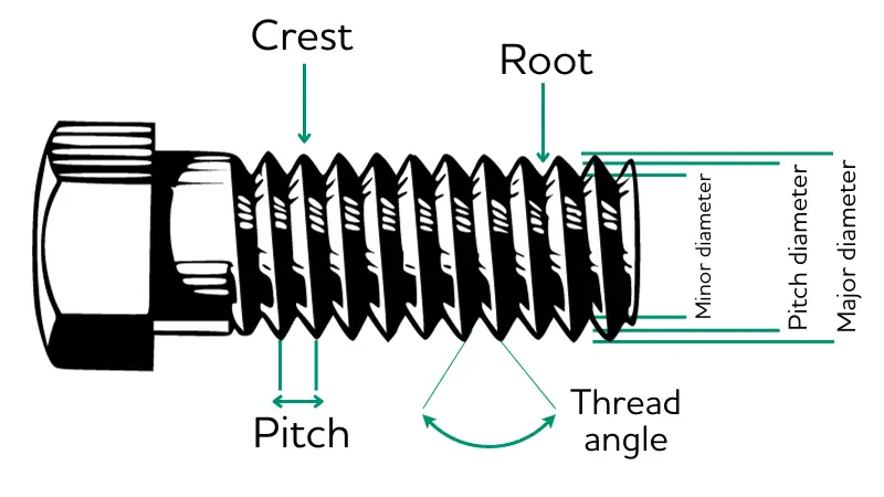
So, the main parameters for indicating threads include pitch, crest, root, thread angle, minor diameter, pitch diameter, major diameter, and depth on blind holes.
Thread types
Tapered thread
A tapered thread has a conical shape as opposed to a cylindrical one. The diameter decreases towards the end. This type of thread achieves a seal through metal-to-metal wedging.
Straight/parallel thread
A straight thread is what you might expect, it has a cylindrical form with a continuous diameter. Where a seal is needed, it’s usually achieved with an O-ring.
Blind hole or through hole
A through hole does what it says on the tin, with the internal thread going all the way through the component. Therefore, the depth of the thread is already predefined as the thickness of the material.
A blind hole does not go all the way through and consequently, you must specify the depth.
Design considerations for machining threads
Standard drill sizes
When designing your thread, it’s important to bear standard drill sizes in mind. Custom tooling is a surefire way to add unnecessary cost and time to production.
A good CNC machining company should be able to guide you on this at the design stage to ensure you achieve the most efficient production possible.
Countersink
For internal threads, ensure you specify a countersink at the end. This small feature has two key functions. Firstly, it aids the alignment of the mating components, ensuring a smoother and more accurate assembly.
By chamfering the end of the internal thread, you can create a tapered surface that guides the mating part into place, reducing the risk of misalignment and cross-threading.
Secondly, a well-executed countersink will promote the longevity of the threaded connection. By dispersing stress and reducing the likelihood of stress concentration at the thread’s termination point, it can help prevent premature thread wear.
Coarse vs fine
Coarse threads are characterised by fewer threads per inch than fine threads. Coarse threads are generally faster to machine and more cost-effective. They provide robust engagement, enhancing the part’s overall strength and durability.
Conversely, fine threads have a higher number of threads per inch and excel in precision and finer adjustments. They are often preferred when the primary concern is achieving a high level of accuracy.
The choice between coarse and fine threads ultimately hinges on the specific requirements of the project; while coarse threads optimise speed and strength, fine threads are the go-to option for applications demanding precision and a high degree of control.
Keep to industry standard
Above I covered the different series of threads. Keeping to industry standard can be a great way of saving time and money. I would generally keep to UN or M except where your industry might require otherwise.
Thread length
I recommend designing threads with a maximum length of three times the diameter of the hole. Any longer than this may cause the part to fail and is likely to increase costs and machining time.
Tolerancing
Tolerancing is vital for the fit and functionality of your threaded components.
ISO 965 tolerances are based on thread coarseness (fine, medium, coarse) and thread engagement length (short, normal, long).
For a standard ISO 965 thread i.e. for a normal commercial application, you would generally specify medium coarseness and normal length.
This would be designated as 6H/6g for an assembly, where 6H denotes the internal thread and 6g denotes the external thread.
If you don’t specify tolerances on your drawing, a CNC machining supplier will normally default to 6H and 6g.
Material selection
It’s important to select two compatible materials that will be mated together in a thread. Some materials don’t work well together, others need very specific tolerancing to ensure they do not fuse together.
It’s worth seeking the expertise of an experienced CNC machining company to help guide you in the material selection process.
Partner with Penta
As you can probably tell, there are a lot of considerations when it comes to specifying threads for CNC machining. Working closely with a CNC machining partner can save you a lot of time, money, and stress.
Here at Penta Precision, we are happy to provide machining design advice as standard.
Ready to get the ball rolling? Give my team a call today on 023 9266 8334 or fill in our form to request a quote.
Not getting what you want from your CNC machining supplier?