CNC machining tolerances define how much variation is allowed on a machined feature while still allowing the part to fit, function and be inspected correctly. They affect almost every practical outcome of a CNC project, including assembly, repeatability, quality control, lead time, and cost.
Key takeaways
- CNC machining tolerances define the acceptable variation allowed on a machined feature, so the part can fit, function and be inspected correctly.
- Tight tolerances should be applied where they protect fit, function, safety, sealing, alignment or interchangeability. Applying them everywhere can increase machining cost, inspection time and lead time.
- General tolerances such as DIN ISO 2768-mK are useful for non-critical features, but critical holes, shafts, datums, sealing faces and assembly interfaces should be individually toleranced.
- Material, geometry, workholding, finishing, tool wear and inspection method all affect how realistic a tolerance is in production.
- The best way to reduce tolerance-related problems is to review the drawing with your CNC machining supplier before quoting, especially for tight tolerance parts, prototypes, repeat batches or safety-critical components.
Want to check if your tolerances are realistic for CNC machining?
What are CNC machining tolerances?
A CNC machining tolerance defines the amount of variation allowed from a specified dimension, shape, position or feature. It tells the machinist what range is acceptable and tells the inspector how the finished part should be measured.
For example, if a hole is specified as 10.00 ±0.05 mm, the finished hole may be accepted between 9.95 mm and 10.05 mm, provided all other drawing requirements are met.
Tolerances are needed because every manufacturing process has controlled variation. Even with accurate CNC machines, the final result can be affected by material movement, workholding, tool wear, heat, vibration, finishing processes and inspection method.
Tolerances are commonly shown as plus/minus values, but they may also be shown as upper and lower limits, unilateral tolerances, ISO fit classes, or geometric tolerances such as flatness, position, perpendicularity,. and profile.
Tighter tolerances are usually specified when there are mating parts, where the component is safety-critical, or is part of a complex assembly. Specifying the correct tolerance will improve the fit and function of your part.
For context, a tight tolerance is typically ± 0.005”, although ±0.001” can be achieved.
Why tolerances matter in CNC machining
Tolerances matter because they control whether a part will work in the real assembly, not just whether it looks correct on its own. A component may appear visually acceptable but still fail if a hole is out of position, a bore is too small, a sealing face is not flat enough, or a shaft does not fit its mating part.
For design engineers, tolerances help protect design intent. They make it clear which features are function-critical and which dimensions have more flexibility.
For procurement teams, tolerances affect price, lead time, and supplier selection. A drawing with tight tolerances across every feature may receive higher quotes because suppliers must allow for more controlled machining and inspection.
For quality teams, tolerances define how parts will be checked and accepted. If the drawing does not make the inspection requirement clear, goods-in issues, rework or supplier disputes become more likely.
For operations teams, tolerances affect repeatability across batches. A tolerance that can be achieved once on a prototype may need further process control to be held consistently across repeat production.
What is a default machining tolerance?
A CNC machining supplier will usually work to a default tolerance standard when no feature-specific tolerance is stated on the drawing. At Penta Precision, our default general tolerance is DIN ISO 2768-mK unless a customer drawing specifies otherwise.
DIN ISO 2768 is used to define general tolerances on engineering drawings where individual tolerances are not listed for every feature. It helps keep drawings clear by applying a standard tolerance class to non-critical dimensions.
In DIN ISO 2768-mK, the “m” refers to the medium tolerance class for general linear and angular dimensions. This can apply to features such as external sizes, internal sizes, diameters, radii, chamfers, and step sizes.
The “K” refers to the general geometrical tolerance class. This can apply to characteristics such as straightness, flatness, perpendicularity and symmetry where no individual geometric tolerance is stated on the drawing.
General tolerances are useful for non-critical features, but they should not replace proper tolerance specification for critical fits, datum features, sealing faces, bearing locations, sliding interfaces or safety-critical features.
Example: when a general tolerance may be suitable
A general tolerance may be suitable for an external profile that does not mate with another component, a non-critical clearance face, or a cosmetic surface where exact dimensional control is not required for performance.
Example: when a feature-specific tolerance is needed
A feature-specific tolerance is usually needed for a bearing bore, shaft fit, dowel hole, precision mounting face, sealing surface, sliding interface, datum feature, or any feature that controls how the component assembles or functions.
ISO 2768 vs ISO 286 vs GD&T: what should you use?
Different tolerance systems are used for different purposes.
ISO 2768 is commonly used for general tolerances on linear, angular and geometrical features where no individual tolerance is shown. It is useful for non-critical dimensions because it keeps drawings readable without tolerancing every feature separately.
ISO 286 is used for limits and fits, especially holes and shafts. It is more suitable when a cylindrical feature needs a controlled clearance, transition fit or interference fit with another component.
GD&T, or geometric dimensioning and tolerancing, controls the shape, orientation, position and relationship of features. It is useful when function depends on more than a simple size tolerance, such as hole position relative to a datum, flatness of a sealing face or perpendicularity of a mounting surface.
As a practical rule, use general tolerances for non-critical features, use ISO fits for controlled mating holes and shafts, and use GD&T where the relationship between features is critical to assembly or performance.
Not getting what you want from your CNC machining supplier?

Why not specify tolerances everywhere?
Tight tolerances should be used where they protect the function of the part. Common examples include bearing fits, sliding fits, sealing faces, precision hole positions, datum features, safety-critical interfaces and parts that must be interchangeable across batches.
Specifying tight tolerances everywhere can create unnecessary cost. The tighter the tolerance, the more control is usually needed during machining and inspection. This can mean slower machining, additional finishing passes, more robust workholding, extra in-process checks, specialist measuring equipment and a higher risk of scrap or rework.
For non-critical faces, cosmetic surfaces, clearance features and dimensions that do not affect assembly, a general tolerance may be more appropriate. This gives the machinist enough control to produce a reliable part without adding avoidable time and cost.
Do tight tolerances increase CNC machining cost?
Yes, tight tolerances usually increase CNC machining cost because they require more process control. This can include slower cutting, extra finishing passes, more stable fixturing, tighter tool wear management, additional inspection and more experienced programming.
The cost is justified when the tolerance protects the part’s function. Examples include bearing fits, sealing surfaces, positional relationships, sliding features and safety-critical interfaces.
If the feature is non-critical, a tight tolerance may increase cost without improving performance. In those cases, a general tolerance such as DIN ISO 2768-mK may be more appropriate.
If a tight tolerance is driving cost, send us your drawing. We can help identify whether the tolerance is function-critical or whether a more practical specification could achieve the same outcome.
What affects achievable CNC machining tolerances?
The tolerance written on the drawing is only one part of the picture. Whether it can be achieved repeatably depends on how the part behaves during machining and how the process is controlled.
Material behaviour
Material choice has a direct effect on how realistic a tolerance is in production. The drawing tolerance may be the same, but the difficulty of achieving it can vary significantly between materials.
Some engineering plastics can move during and after machining because they are more affected by heat, moisture absorption and internal stress. Thin plastic features may also deflect during cutting, making tight tolerances harder to hold consistently.
Aluminium is generally easier to machine accurately, although thin walls and deep pockets can still move if the part is not designed and fixtured carefully. Stainless steel, titanium and other tougher materials may require slower machining strategies, sharper tooling, controlled workholding and careful inspection planning.
This is why material selection and tolerance specification should be reviewed together. A tolerance that is practical in one material may be more expensive, slower or less repeatable in another.
Part geometry
Geometry can make a tolerance easier or harder to hold. Deep pockets, long slender features, thin walls, interrupted cuts and features that require multiple setups can all increase risk.
A tight tolerance on a rigid, accessible feature may be straightforward. The same tolerance on a thin wall or deep internal feature may be much harder to hold because the material can deflect during cutting or move after it is released from the fixture.
Workholding and datum strategy
Workholding controls how the part is located, supported and restrained during machining. If the part is not held securely or if the datum scheme is unclear, variation can be introduced between setups.
Clear datum references are especially important where hole positions, flatness, perpendicularity or relationships between features matter. If a drawing does not define the datum structure clearly, the supplier may need to ask questions before quoting or machining.
Tool wear, heat and vibration
Cutting tools wear during machining. Heat can build up in the material and tooling. Vibration can affect surface finish and size control. These factors are manageable, but they become more important as tolerances get tighter.
For tight tolerance CNC machining, the supplier may need to control tool life carefully, use stable cutting conditions, plan finishing passes and inspect key features during production rather than only at the end.
Surface finishing
Finishing processes can change the final dimensions of a machined component. Anodising, plating, passivation, bead blasting and other finishing processes may affect surface thickness, edge condition, cosmetic appearance or how a part fits with another component.
For example, anodising can add or alter surface build-up. If a bore, thread, sliding fit or sealing surface is finished after machining, the final size may differ from the machined size. This needs to be considered before tolerances are finalised.
Where the finished dimension is critical, the drawing and purchase order should make this clear. The machining supplier can then plan whether to machine before finish, mask certain features, adjust the pre-finish size, or inspect after finishing.

Inspection method
A tolerance also needs to be measurable. If a drawing specifies a very tight tolerance, the supplier must be able to inspect it using an appropriate method.
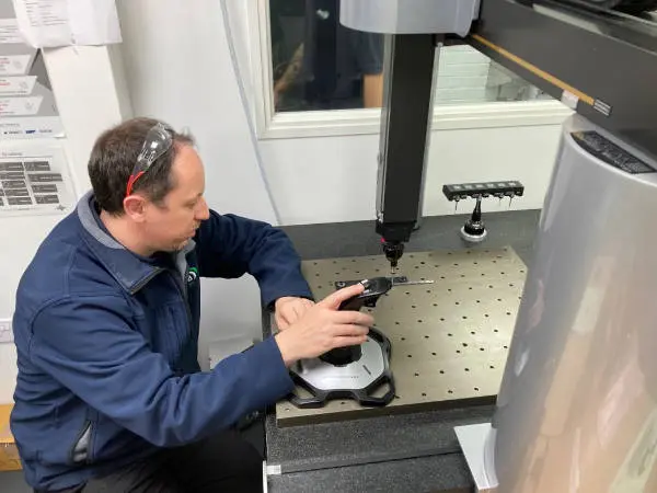
Depending on the feature, this may require micrometers, bore gauges, height gauges, optical measurement, surface finish measurement or CMM inspection. For quality-critical work, it is important to agree what will be inspected, how it will be measured and what evidence will be supplied with the parts.
Prototype versus repeat production
A tolerance that can be achieved on one prototype may need more control for repeat production. As quantities increase, process stability matters more. The supplier needs to consider tool wear, batch consistency, fixture repeatability, inspection frequency and how the process will be maintained over time.
For prototype work, the priority may be proving form, fit and function quickly. For production work, the priority is repeatability across the batch and across future orders.
How to specify tolerances for CNC machining
Start by identifying the features that affect fit, function, safety, sealing, alignment, or interchangeability. These features should be toleranced deliberately rather than left to a general tolerance note.
For non-critical dimensions, use a clear general tolerance standard such as DIN ISO 2768-mK. This keeps the drawing readable and avoids adding unnecessary cost to features that do not affect performance.
Next, review the tolerance stack across the assembly. A single feature may look acceptable in isolation but create a problem when combined with mating parts, fasteners, finishes and assembly clearances.
You should also confirm the finish before finalising tolerances. If the part will be anodised, plated, bead blasted or passivated, decide whether the critical dimension applies before or after finishing.
Finally, agree the inspection requirement. For tight tolerance or quality-critical parts, confirm which features need inspection evidence, whether a CMM report is required, and what documentation should be supplied with the order.
Practical tolerance checklist for CNC drawings
Before sending a drawing for quote, check whether it answers these questions:
- Which features control fit, function, sealing, movement or alignment?
- Which dimensions can follow a general tolerance?
- Does the drawing state the general tolerance standard?
- Are datum features clearly defined?
- Are hole and shaft fits specified where needed?
- Does the finish affect any critical dimensions?
- Are inspection requirements clear?
- Is the drawing issue correct and controlled?
- Are there any tolerances that may add cost without improving performance?
Common tolerance problems in CNC machining
Tolerance problems usually come from one of two directions: the drawing does not communicate the functional requirement clearly, or the machining process cannot repeatedly achieve what has been specified.
Common causes include over-tight tolerances on non-critical features, no tolerance stated for a critical fit, unclear datum references, tolerance stack-up across an assembly, material movement, finishing thickness, or inspection requirements that were not agreed before production.
These issues can lead to parts that are technically made to drawing but still fail at assembly, or parts that are rejected because the drawing did not reflect how the component would be manufactured and inspected.
The safest approach is to identify the critical features before quoting. Mark the features that control fit, movement, sealing, alignment or safety, then ask your CNC supplier to confirm whether the specified tolerances are realistic for the material, geometry, batch size and inspection method.
What happens if tolerances are specified incorrectly?
If tolerances are too loose, parts may not fit, align, seal or function correctly. This can lead to assembly delays, rework, rejected parts, or failures in use.
If tolerances are too tight, the part may become unnecessarily expensive or slow to manufacture. It may also increase inspection time and raise the risk of avoidable non-conformance.
The most common issue is applying the wrong level of control to the wrong feature. Critical features should be clearly identified. Non-critical features should not be over-controlled.
What should you ask your CNC supplier about tolerances?
Before placing an order, ask your CNC supplier:
- Which features on this drawing are likely to drive cost?
- Are any tolerances difficult to hold in the chosen material?
- Will the finishing process affect any critical dimensions?
- Which features will be inspected, and how?
- Can the tolerance be held consistently across the full batch?
- Would a small design change improve repeatability or reduce cost?
For engineering teams, this reduces design iteration. For procurement teams, it reduces quote ambiguity and supplier risk. For quality teams, it helps ensure inspection expectations are agreed before parts arrive at goods-in.
How Penta supports tolerance-critical CNC parts
At Penta Precision, tolerance advice starts with understanding the function of the component. When you share a drawing, CAD model and project requirements, we can review the features that are likely to affect manufacturability, inspection, cost and repeatability.
Our team can help you identify which dimensions need tighter control, which can follow a general tolerance and where a drawing clarification could prevent issues later. This is especially valuable for parts with tight fits, thin walls, small features, complex geometries, specialist materials or post-machining finishes.
We can also advise on inspection requirements, including which features may need CMM inspection or additional evidence. For quality-critical work, agreeing this upfront helps reduce goods-in queries, rework and delays.
In conclusion
CNC machining tolerances are not just drawing details. They influence whether a part fits, functions, can be inspected and can be produced repeatably at a sensible cost.
The best results come from applying tight tolerances where they are needed and using clear general tolerances where they are not. Critical features should be defined properly, material and finishing effects should be considered early, and inspection expectations should be agreed before production begins.
If your component includes tight fits, sealing faces, thin walls, precision hole positions or post-machining finishes, reviewing the tolerances before quoting can prevent avoidable cost, delay and rework.
We're ready to help you with your project.