Key Takeaways
- Strong CAD machining practices lead to faster quotes, fewer design revisions, and better machining results.
- A clear, accurate CAD file is critical to avoiding errors, delays, and unnecessary costs in CNC projects.
- Designing with manufacturability in mind improves part quality and helps streamline production.
- Applying realistic tolerances, choosing practical materials, and clearly specifying critical features reduces risk and cost.
- Preparing CAD files with common formats, detailed 2D drawings, and clear labels supports efficient manufacturing.
CAD machining plays a huge part in getting CNC projects right the first time. When your design files are clear, precise, and ready for production, you’ll enjoy better quotes, quicker turnaround times, and parts that meet your exact specs. This guide will help you get the most out of CAD machining, making your CNC projects smoother and more successful.
What Is CAD Machining?
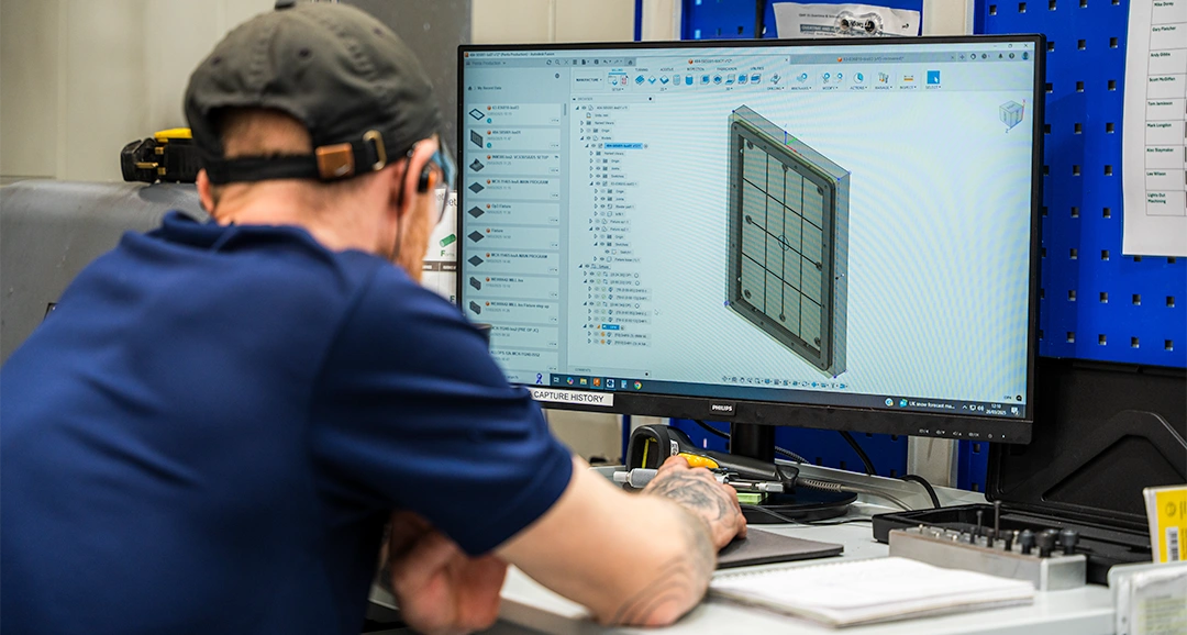
CAD machining is where every CNC project begins. You create a CAD model that acts as the blueprint for everything from toolpaths to the finished part. With smart CAD machining, you make sure your design transfers smoothly from screen to reality.
CAD vs. CAM vs. CNC
CAD, or computer-aided design, is the software you use to create a digital model of your part. CAM, which means computer-aided manufacturing, converts that model into toolpaths and G-code for the CNC machine. The CNC machine follows these coded instructions to cut and shape the part, bringing your CAD machining project to life.
How Cad Files Drive CNC Machining
Your CAD file drives the entire CNC machining process. It contains the critical dimensions, tolerances, and features needed for accurate machining. Without a clear CAD file, your CAD machining project risks errors, delays, and added costs.
Key Benefits of Strong CAD Machining Practices
Strong CAD machining practices help you avoid costly mistakes, streamline production, and improve part quality. They also make it easier for your CNC supplier to work efficiently with your designs. Here’s why getting your CAD machining right matters.
Faster, More Accurate Quotes
Well-prepared CAD files allow suppliers to quote quickly and with confidence. With clear specifications, they don’t need to chase you for missing information. This often leads to quicker project starts with trusted CNC machining services.
Fewer Design Revisions
Designing with manufacturing in mind means fewer unexpected issues down the line. You reduce the risk of costly design revisions that slow everything down. Working with a partner who offers design for manufacture support helps you spot potential problems before they affect production.
Improved Machining Results
Good CAD files lead to better toolpaths, tighter tolerances, and smoother machining. This helps ensure your parts meet both visual and functional requirements. You can also use our guide to geometric dimensioning and tolerancing to fine-tune your CAD models before production.
Reduced Costs and Lead Times
Strong CAD machining practices save both time and money by:
- Reducing the risk of machining errors and costly rework
- Cutting down on the need for multiple design revisions
- Speeding up production and delivery schedules
Good design choices also help shorten CNC machining lead times, which can make a big difference to your project’s overall success.
How CAD Machining Works in a CNC Workflow
Understanding where CAD fits into the CNC workflow shows why it matters so much. Each stage builds on the last, and a strong CAD design lays the groundwork for a successful project. Here’s how it works in a typical CAD CNC machine process.
Design Stage (CAD Software)
Every CNC project starts with creating a digital model of your part in CAD software. This is where you set the dimensions, tolerances, and features your design needs. Thinking about manufacturability at this stage can save time, money, and reduce problems later on.
Toolpath Generation (CAM Software)
Your CAD model is brought into CAM software, where the toolpaths for the CNC machine are created. These toolpaths are then converted into G-code, the set of instructions that control the machine’s movements. A strong CAD design for CNC machine processes ensures toolpaths are accurate, efficient, and ready for production.
Machining Execution (CNC Machine)
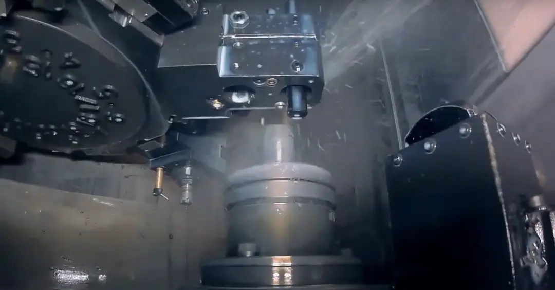
The CNC machine follows the G-code to machine the part. Precision at this stage depends on the quality of the CAD and CAM setup. With the right preparation, your CAD machine process delivers consistent, high-quality results.
Best Practices for CAD Machining Design
Good design practices make all the difference in CNC machining. They help you avoid production headaches and ensure your parts are made right the first time. Here are some key principles to follow when preparing your CNC machining guide.
Design For Machinability
Designing for machinability means knowing the limits and strengths of CNC machines. Overly complex features can drive up costs or make parts difficult to produce. Keeping your design practical saves time, reduces expense, and improves results in CAD machining projects.
Apply Sensible Tolerances
Tight tolerances should be used only when truly necessary. Applying them across the entire design can increase machining time and push up costs. Talking through your needs with a supplier experienced in specifying threads for CNC machining helps you avoid over-specifying.
Choose Practical Materials
Your choice of material affects machining speed, tool wear, and overall cost. Some materials are easier to machine, while others may require specialist tools or longer lead times. Choosing materials for CNC machining carefully can make a big difference to both your design and your budget.
Specify Critical Features
Make sure you clearly highlight critical features in your CAD files and technical drawings.
- Label key dimensions, threads, and surfaces that must meet exact specifications.
- Use notes and callouts to avoid confusion during machining. This approach improves accuracy and helps reduce costly mistakes in CAD machining processes.
Preparing CAD Files for Your CNC Supplier
Providing the right CAD files helps your project run smoothly and reduces the risk of costly errors. The more complete and accurate your files are, the easier it is for your supplier to deliver exactly what you need. Here are three simple ways to prepare your CAD CNC machine files.
Include 2D Technical Drawings
2D technical drawings give details your CAD model alone may not capture. They show critical information like tolerances, surface finishes, and other specifications that help avoid confusion. Including these drawings reduces the risk of machining errors in CAD machining projects.
Use Common File Formats
Using standard file formats such as STEP, IGES, or DXF makes it easier for your supplier to work with your design. Proprietary formats often cause compatibility problems and lead to unnecessary delays. Choosing the right format helps streamline CAD design for CNC machine projects and keeps production on track.
Label Features Correctly
Clearly labelling critical features, threads, and surfaces in your CAD files helps prevent mistakes during machining. Adding notes and callouts ensures your supplier understands exactly what’s required. This level of detail improves the overall success of your CAD machine project.
Working with a CNC Machining Partner
Choosing the right CNC machining partner isn’t just about placing an order, it’s about building a relationship with a team that understands your industry, your materials, and your specific project goals. A good partner helps you avoid common pitfalls and makes the production process easier from start to finish. Penta Precision provides CNC machining services built on quality, reliability, and expert support every step of the way.


