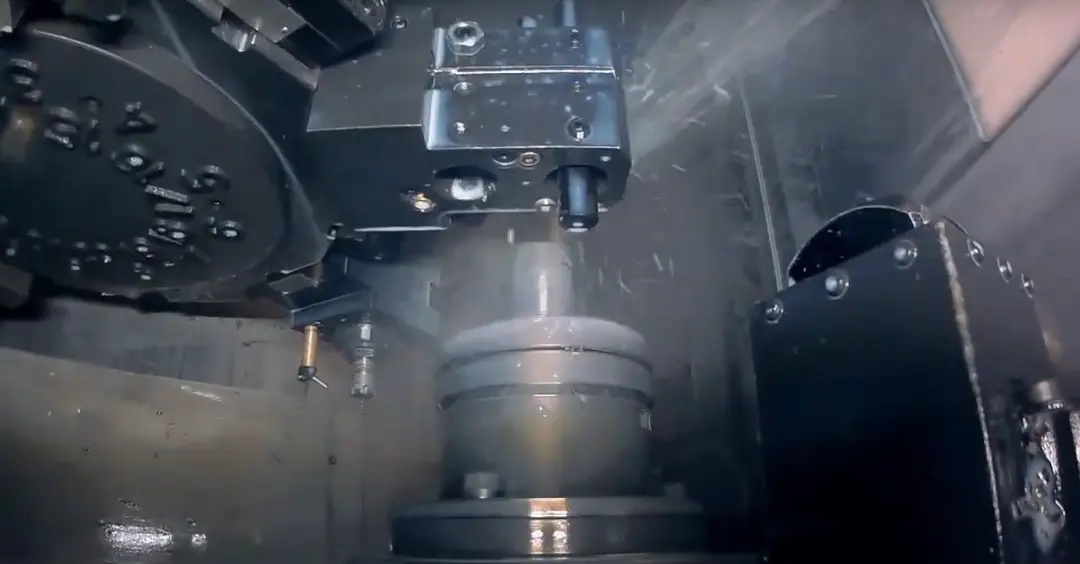
Tolerancing errors are one of the most common reasons for quality issues in manufacturing. In CNC machining, even small tolerance mistakes can lead to part failures, rework, or costly delays. If you work with CNC-machined components, understanding how different types of tolerance work could save you both time and money.
Unilateral and bilateral tolerances control how much variation is allowed when manufacturing a part. The way these tolerances are applied affects the part's fit, function, and manufacturability. Understanding the difference between bilateral vs unilateral tolerance helps ensure parts are produced accurately and perform as intended.
Key Takeaways
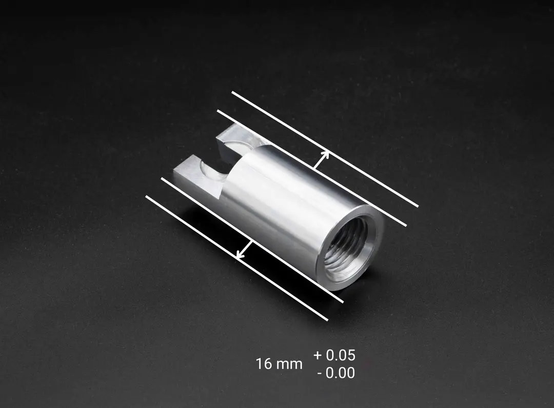
- Unilateral tolerance allows variation in one direction only. For example, 16 mm +0.05/-0.00 means the feature can be slightly larger than 16 mm, but not smaller. This is useful when one boundary must be protected for fit, clearance, assembly, or function.
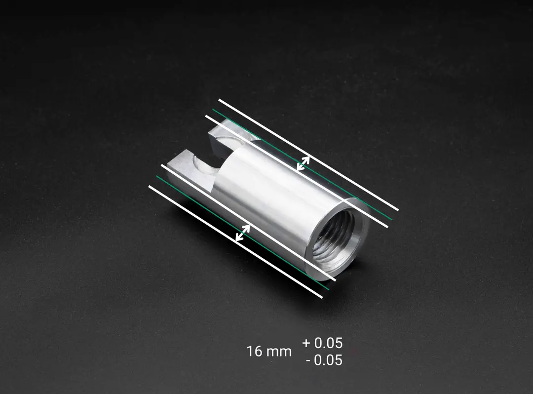
- Bilateral tolerance allows variation above and below the nominal dimension. For example, 16 mm ±0.05 means the feature can measure between 15.95 mm and 16.05 mm. This is common when equal variation in either direction will not stop the part working.
- The right tolerance type depends on the function of the feature. Critical mating features, press fits, sliding fits, sealing faces, datum-related features, and inspection-critical dimensions need tighter thought than non-critical faces or cosmetic features.
- Unilateral tolerance is not automatically “better” or “more precise”. A 16 mm +0.10/-0.00 unilateral tolerance and a 16 mm ±0.05 bilateral tolerance both create a 0.10 mm total tolerance zone. The difference is where that tolerance zone sits relative to the nominal size.
- Poor tolerance choices increase CNC machining cost and risk. Overly tight or poorly placed tolerances can lead to extra setups, slower machining, higher inspection effort, more scrap, and avoidable drawing clarification.
We're ready to help you with your project.

What is Unilateral Tolerance?
A unilateral tolerance places the entire allowable variation on one side of the nominal dimension. For example, a 16 mm +0.05/-0.00 tolerance means the finished feature may measure between 16.00 mm and 16.05 mm, but it cannot be smaller than 16.00 mm. This is useful when one dimensional boundary must be protected for fit, clearance, assembly, or function.
Characteristics
A unilateral tolerance allows the manufactured feature to vary in one direction from the stated nominal size. For example, a shaft specified as 10 mm +0.00/-0.10 may measure from 9.90 mm to 10.00 mm, but it must not exceed 10.00 mm. This helps protect functional limits where too much or too little material could affect fit, movement, clearance, or assembly.
The tolerance is typically expressed as +0.00/-0.10, +0.10/-0.00, or another one-sided limit depending on the functional requirement. It is commonly used when a component must not exceed a maximum size or fall below a minimum size. Inspectors still check that the measured feature sits within both stated limits, but the one-sided notation makes the design intent clearer.
This directional control helps improve reliability across mating components where one side of the tolerance zone is more important than the other. For example, if a shaft must slide into a hole, the shaft may need a maximum permitted diameter so it does not become too tight. In that case, a unilateral tolerance can make the functional boundary clear on the drawing.
Applications & Examples
Unilateral tolerance is often used where a feature has a strict maximum or minimum functional limit. A common example is a shaft, pin, bore, slot, or mating feature where too much variation in one direction could prevent assembly or change the intended fit. The tolerance can be positioned so the finished feature remains within the required functional boundary.
This approach is often used in sectors like aerospace, medical, and automotive manufacturing. It's especially useful in parts that require consistent assembly or support load without deformation. Where materials may expand due to heat or stress, unilateral control helps preserve critical dimensions.
Inspection still needs to confirm that the measured feature falls between the upper and lower limits shown on the drawing. The benefit of unilateral tolerance is not that only one limit is checked, but that the functional limit is made explicit. For tightly fitted assemblies, this helps machinists and inspectors understand which side of the nominal dimension is most important to protect.
What is Bilateral Tolerance?
A bilateral tolerance allows variation above and below the nominal dimension. For example, a 16 mm ±0.05 tolerance means the finished feature may measure between 15.95 mm and 16.05 mm. This is useful when the part can still assemble, locate, seal, or operate correctly if the feature is slightly larger or smaller than the nominal size.
Characteristics
A bilateral tolerance forms a tolerance zone that extends in both directions from the nominal size. For instance, a part specified as 25 mm ± 0.2 mm can range from 24.8 mm to 25.2 mm. This range helps accommodate typical machining variation while keeping the part within acceptable limits.
Typically, the tolerance is evenly distributed, but it can be adjusted to favour one side. This is known as unequally disposed tolerance and is useful when one direction allows for more deviation than the other. It's a flexible approach when design intent permits more variation on one side of the nominal dimension.
Bilateral tolerances are easy to interpret and widely used across engineering drawings. They are suitable when acceptable variation can sit on both sides of the nominal dimension, including some functional features where the tolerance range has been correctly specified. Common examples include mounting plates, covers, brackets, housings, and other CNC machined features where controlled variation in either direction is acceptable.
Applications & Examples
A common bilateral tolerance example is a housing cover, bracket, plate, or spacer that can be slightly larger or smaller while still meeting the assembly requirement. The important point is not whether the part is critical or non-critical, but whether variation on both sides of nominal is acceptable for the feature’s function. Where this is true, bilateral tolerance can support reliable CNC machining without over-restricting the process.
You will frequently see bilateral tolerances on general machined features, non-mating components, mounting details, covers, spacers, and cosmetic surfaces. They are also used on functional features when the drawing allows controlled variation above and below nominal. In production, the cost benefit comes from using an appropriate total tolerance range, rather than from the bilateral format alone.
Bilateral tolerance is also well-suited to components made from plastics or composites. These materials may expand or shrink unpredictably, and the two-way flexibility helps maintain dimensional integrity. This approach strikes a balance between manufacturability and reliable function.
Key Differences Between Unilateral and Bilateral Tolerances
While both tolerance types serve the same goal, dimensional control, they apply it in different ways. Each method has specific strengths depending on how the part functions in an assembly. Understanding when and why to use them helps you avoid costly design and manufacturing issues.
Direction of Variation
The core difference lies in the direction each tolerance type allows variation from the nominal size. Unilateral tolerances permit deviation in only one direction—either above or below the base size. Bilateral tolerances allow variation in both directions, offering a more balanced tolerance zone.
This difference matters in assemblies where clearance or interference fits are critical. Too much variation in both directions can lead to parts being too loose or too tight. That's why unilateral tolerance is often preferred in high-precision fits.
Bilateral tolerances are suitable when the feature can vary above or below nominal without compromising fit, function, inspection, or assembly. They are often used on non-mating or less sensitive features, but they are not limited to those applications. They can also be used on functional CNC machined features when the permitted tolerance range has been defined correctly.
Engineering Drawings
Unilateral and bilateral tolerances are clearly marked on technical drawings for CNC machining. A unilateral tolerance might be shown as +0.00/-0.10, while a bilateral would appear as ±0.05. These notations ensure machinists and inspectors understand the exact dimensional limits.
In drawings using Geometric Dimensioning and Tolerancing (GD&T), extra symbols like "U" may indicate unequally disposed tolerances. This shows when a bilateral tolerance is intentionally offset more to one side. Accurate notation is essential for maintaining clarity between design and production.
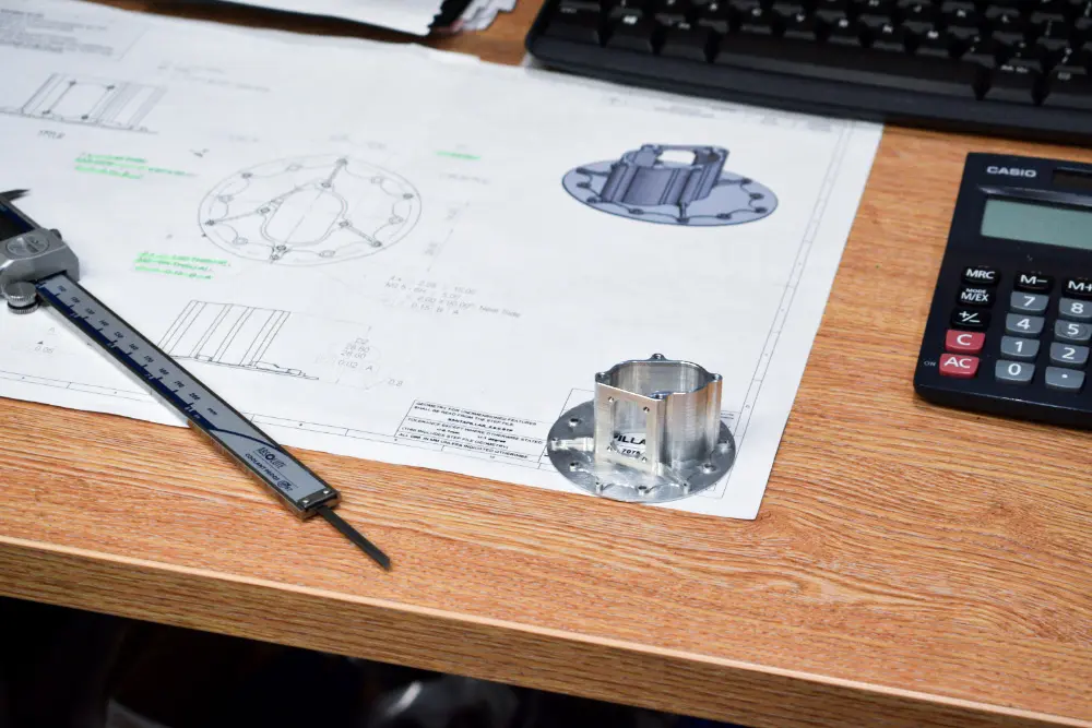
Using a reliable machining drawing service helps ensure these tolerances are applied correctly. It reduces the chance of miscommunication and machining errors. Precise documentation leads to better part quality and fewer delays.
Need advice on your engineering drawing?
Impact on Precision & Quality
Unilateral tolerances offer clearer control of a maximum or minimum functional boundary. This can support consistent assembly where too much variation in one direction would affect fit, movement, clearance, or performance. The one-sided limit helps communicate which side of the nominal dimension must be protected.
Bilateral tolerances also support quality when the tolerance range is appropriate for the feature. They allow controlled variation above and below nominal, which can be suitable for both general features and functional features. The key is to match the tolerance range and tolerance position to the part’s design intent.
Choosing the correct type of tolerance helps maintain precision where it matters most. It also supports consistent production outcomes and part reliability. Good tolerance planning contributes directly to part quality and product lifespan.
Cost & Production Efficiency
Unilateral tolerances do not automatically cost more than bilateral tolerances. Cost is driven mainly by the total tolerance width, material, feature geometry, setup complexity, surface finish, inspection requirements, and process capability. A unilateral tolerance may increase cost when it creates a tighter or harder-to-hold manufacturing window, but the one-sided format alone is not the cost driver.
Bilateral tolerances can support efficient production when the total tolerance range is practical for the machining process. They do not always provide a wider margin of error than unilateral tolerances because two tolerances can have the same total tolerance band. For example, 16 mm +0.10/-0.00 and 16 mm ±0.05 both allow 0.10 mm of total variation, but the tolerance zones are positioned differently.
Making smart tolerance choices directly affects production costs. Overly tight tolerances can lead to unnecessary rework and longer lead times. By matching tolerance type to part function, you can optimise both quality and workflow.
Suitability for Applications
Unilateral tolerance works well where a feature has a strict upper or lower functional boundary. This can include shafts, bores, pins, slots, sealing faces, sliding fits, press fits, and other mating features. It is especially useful when variation in one direction creates more risk than variation in the other.
Bilateral tolerance suits features where controlled variation above and below nominal is acceptable. You will often see it on control panels, covers, faceplates, brackets, housings, spacers, and general machined details. It can also be used on functional features when the designer has confirmed that the full upper and lower limit range will still meet the assembly requirement.
Material properties also influence which tolerance type to use. Metals and plastics respond differently to temperature and stress, requiring different tolerance strategies. Always consider both part function and material behaviour during design.
Common Use Cases
Use unilateral tolerance for features where one side of the tolerance range must be controlled more tightly to protect function. Typical examples include press fits, sliding fits, rotating features, bores, pins, shafts, sealing features, and datum-related dimensions. This is common in CNC machined parts for aerospace, defence, medical, scientific, and industrial applications.
Use bilateral tolerance when the feature can vary in either direction from nominal and still meet the design requirement. Parts such as brackets, spacers, housings, mounting plates, covers, and outer panels often use bilateral tolerances. Inspection still verifies the measured feature against upper and lower limits, but the notation is straightforward and widely understood.
Both tolerance types have a place depending on the part's role in the assembly. Knowing where to use each prevents over-engineering and avoids wasted time or resources. It's all about applying the right control where it matters most.
Quality Control & Inspection
Unilateral tolerances can make inspection intent clearer by showing which side of nominal is functionally constrained. However, inspection still confirms that the measured feature is within the stated upper and lower limits. The practical benefit is clearer communication between design, machining, and inspection, not the removal of one side of the check.
Bilateral tolerances are inspected by checking whether the measured feature falls within the permitted lower and upper limits. This is the same fundamental limit-checking principle used for unilateral tolerances. CMM inspection, gauges, micrometers, bore gauges, and other inspection methods can all be used depending on the feature and drawing requirement.
Accurate inspection starts with clearly defined tolerances on the drawing. The more precise the specifications, the more reliable the quality control process will be. Good tolerancing reduces rejects, rework, and long-term quality issues.
Advantages & Disadvantages
Each tolerance type comes with its own pros and cons depending on your design and manufacturing needs. Understanding these trade-offs helps you choose the most practical and efficient option for your specific application. Below are the key advantages and disadvantages of unilateral and bilateral tolerances.
Unilateral Tolerance
Unilateral tolerance offers clear control of a maximum or minimum functional boundary, making it a strong choice for fits, clearances, sealing features, and other dimensionally sensitive areas. It can improve drawing clarity by showing which side of the nominal dimension matters most. It may increase machining time or cost if the total tolerance range is tight, difficult to hold, or requires additional inspection evidence.
Advantages
- Makes maximum or minimum functional limits clear
- Useful for fits, clearances, bores, pins, shafts, and mating features
- Helps communicate design intent to machinists and inspectors
Disadvantages:
- Can be misunderstood if the drawing does not clearly define the functional requirement
- May increase cost if the total tolerance range is tight or difficult to hold
- Gives less freedom to centre the process around the nominal dimension
Bilateral Tolerance
Bilateral tolerance provides a clear tolerance zone above and below the nominal dimension, making it widely used across CNC machining drawings. It can support efficient production when the tolerance range is suitable for the feature and process. The trade-off is that it may not protect a one-sided functional limit as clearly as a unilateral tolerance.
Advantages
- Simple, familiar notation for engineering drawings
- Allows controlled variation above and below nominal
- Suitable for many general and functional CNC machined features
Disadvantages
- May be unsuitable where one side of the tolerance range is functionally critical
- Can create assembly risk if the upper and lower limits are not checked against the mating part
- May still increase cost if the total tolerance range is unnecessarily tight
Choosing the Right Tolerance
Choosing between unilateral tolerance and bilateral tolerance depends on the function of the feature, not simply whether the part is “critical” or “non-critical”. Use unilateral tolerance when one side of the nominal dimension represents a functional limit that must be protected. Use bilateral tolerance when variation above and below nominal is acceptable for fit, assembly, inspection, and performance.
Consider the role of the part in the assembly and how much variation it can tolerate without affecting performance. Material type, expected thermal expansion, and surface finish also influence which approach to use. Balancing function, manufacturability, and cost is the key to effective tolerance selection.
Your CNC supplier can offer insights based on their capabilities, tools, and inspection methods. A collaborative approach is especially helpful when working with tight tolerances or complex assemblies. Partnering with a trusted CNC machining service helps reduce risk, improve part quality, and ensure a smoother production process.
We're ready to help you with your project.

In Conclusion
Tolerances define the acceptable range of variation in a part's dimensions, which directly impacts function, fit, and manufacturability. They affect how easily parts assemble, how thoroughly they must be inspected, and how costly they are to produce. Getting tolerances right is essential to ensuring consistent, reliable performance in any application.
Bilateral vs unilateral tolerance is about where the acceptable tolerance zone sits relative to the nominal dimension. Unilateral tolerance places allowable variation on one side of nominal, while bilateral tolerance allows variation above and below nominal. The correct choice depends on drawing intent, mating parts, material behaviour, inspection requirements, and how the feature affects the finished component.
Use tighter tolerances only where needed, such as for high-precision fits or load-bearing components. Apply looser tolerances in non-critical areas to save on cost, time, and material waste. This balance also improves communication with machinists and streamlines collaboration with CNC suppliers.