CNC milling is a subtractive manufacturing process in which material is removed from a billet of raw material to create a component. It's an important part of the modern manufacturing process and is typically used during machining.
For engineers, it affects whether critical features can be held consistently, whether surface finish is achievable without extra handling, and whether a design moves cleanly from prototype into repeat production. It also shapes lead time, inspection effort, and the risk of rework when drawings leave too much open to interpretation.
A basic understanding of CNC milling helps you make better decisions at design and quoting stage. It makes it easier to spot where geometry, tolerance strategy, material choice, or setup complexity may create avoidable cost and variation later.
Key takeaways
- CNC milling affects tolerance stability, repeatability, finish quality, lead time, and inspection burden.
- Setup count and datum strategy have a direct impact on alignment risk and geometric consistency.
- 5-axis milling is valuable when geometry demands it, but unnecessary axis capability can increase cost.
- Material choice changes machinability, distortion risk, tool wear, finishing behaviour, and cycle time.
- Good DFM reduces setup count, variability, machining time, and quoting risk.
What is CNC milling?
CNC milling is a machining process where rotating cutting tools remove material from a fixed workpiece using programmed digital instructions. It is used to produce accurate components in metals and plastics, often where flat faces, pockets, slots, holes, and complex profiles are required.
It differs from turning because the workholding and cutting arrangement are different. In turning, the part rotates. In milling, the tool rotates while the part is held in position. That difference matters because it affects how features are accessed, how setups are planned, and how tolerances are controlled.
What CNC milling actually influences in your process
CNC milling is not just a way to shape material. It directly affects how stable the process will be once a part is released for manufacture. If a component needs multiple setups, carries unnecessarily tight tolerances, or includes hard-to-access features, the result is usually more variation, more inspection, and more time spent controlling risk.
That has practical consequences. Setup variation can create alignment issues between related features. Tool access can affect surface finish consistency. Complex geometry or unstable workholding can increase rework risk. Even when parts are technically machinable, the burden on inspection can become disproportionate if the design pushes too much control into measurement rather than process stability.
Key stages of the CNC milling process
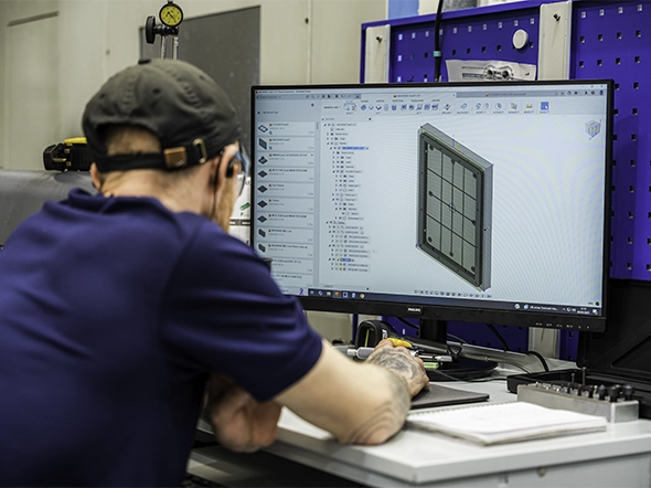
CAD to CAM
At this stage, the drawing or model is translated into machining strategy. The main risk is misinterpretation. Unclear datums, over-defined tolerances, and ambiguous finish requirements force assumptions that can affect sequencing, fixturing, and inspection.
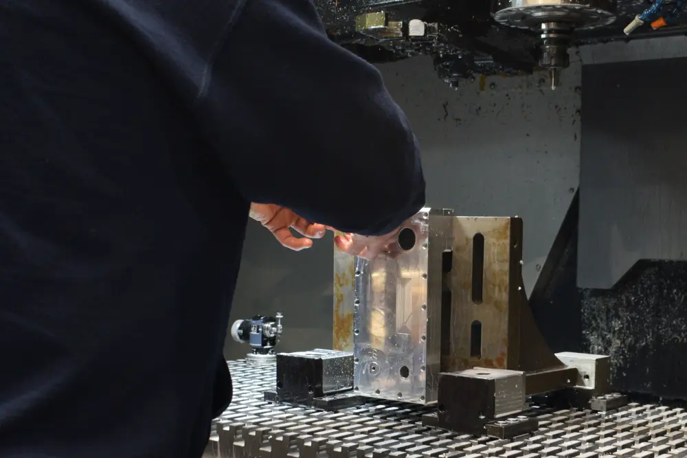
Setup and fixturing
This is where the part is located and clamped for machining. Thin walls, poor datum selection, and limited support can introduce movement or distortion. If the setup is unstable, good programming will not recover the process.
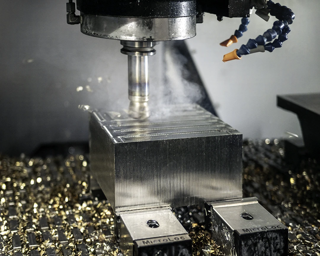
Machining
The chosen tools and toolpaths determine how material is removed. Aggressive cutting may shorten cycle time, but it can also create chatter, heat build-up, burrs, or surface inconsistency, especially on delicate features or harder materials.
Inspection and validation
Inspection confirms whether the process is actually holding the critical features. First-off validation matters because it catches problems before they repeat across a batch. It also determines how much confidence you have in repeatability, not just first-piece accuracy.
Common CNC milling operations
Face milling creates flat reference surfaces and is often one of the first operations because it establishes a controlled base for later machining.
Pocket milling removes material inside enclosed areas. It is common in weight-reduced parts, housings, and features with depth-to-width constraints. Deep pockets often increase tool reach and deflection risk.
Slotting produces straight channels for clearance, location, or assembly features. Narrow slots can restrict tool choice and make burr control more difficult.
Drilling creates holes quickly and accurately, but hole position and entry condition still depend on setup quality and material behaviour.
Tapping cuts internal threads. It is straightforward when hole size, depth, and material are sensible, but thread quality becomes less predictable if wall thickness or chip evacuation is poor.
3-axis vs 5-axis milling: when each makes sense
3-axis milling is often the right choice for parts with features accessible from straightforward directions. It is cost-effective, stable, and entirely suitable for many prismatic components.
5-axis milling becomes useful when geometry includes compound angles, difficult access, or positional relationships that are better maintained in one setup. Reducing setups helps limit alignment shift and tolerance stack across related features.
That does not mean 5-axis should be specified by default. If the part can be machined effectively in fewer axes without compromising function, adding capability may only increase cost and programming effort. The better question is whether the geometry genuinely benefits from fewer repositioning steps.
Materials: what changes in machining terms
When it comes to milling, not all materials are created equal.
Aluminium generally machines efficiently, supports strong surface finish outcomes, and is well suited to parts where cycle time and cosmetic consistency matter. It can, however, move if sections are thin or internal stresses are released during machining.
Stainless steel is more demanding. It typically increases tool wear, extends machining time, and requires more careful control of heat and cutting conditions. It is often chosen for performance reasons, but that choice has cost and lead time implications.
Engineering plastics can machine well, but they behave differently from metals. They may deform more easily, respond differently to clamping pressure, and show movement during machining or inspection. Finish expectations also need to reflect the material, especially if the part will not receive secondary finishing.
Design for manufacture: where reliability starts
DFM is about making a part easier to machine reliably, repeatedly, and at sensible cost. In CNC milling, poor DFM usually shows up as more setups, more tool changes, longer cycle times, and more opportunities for variation.
Common examples include over-tight tolerances on non-critical features, thin walls that deflect under cutting load, deep pockets that need long tools, inaccessible areas that force awkward setups, and datum schemes that do not reflect how the part can actually be held and inspected. Surface finish can create the same problem when it is specified more tightly than function requires.
These issues do not just affect machining. They increase quoting uncertainty, raise inspection effort, and make it harder to achieve stable results batch after batch. Good DFM removes unnecessary complexity while protecting the features that matter.
We're here to support you with DfM
Common CNC milling misconceptions
Many buyers assume 5-axis always produces better parts because it sounds more advanced. In reality, it is better only when the geometry benefits from fewer setups or improved access.
Tighter tolerances are also often treated as a safe default. They are not. Unless a tighter tolerance protects fit, function, or downstream assembly, it usually adds machining and inspection cost without improving the part.
Fast lead times can be misunderstood in the same way. A realistic lead time often reflects proper planning, validation, and inspection. Compressing that process too far can increase variation rather than reduce it.
What drives cost in CNC milling
Cost rises when a part is harder to produce consistently. More setups, more complex geometry, tighter tolerances, difficult materials, extra tool changes, finishing requirements, and heavier inspection all add time and control burden. Batch size matters too. Small quantities carry more setup cost per part, while repeat batches benefit from process reuse.
The important point for engineers is that many of these drivers are influenced at design stage. Rationalised tolerances, accessible features, sensible material selection, and clearer datum strategy often reduce cost without changing function.
How to choose a CNC milling partner
For engineers and technical buyers, supplier selection should go beyond machine list and headline lead time. Look for evidence of drawing review quality, practical risk identification before machining, robust fixturing and process control, inspection capability, and realistic communication when assumptions need clarification.
It also helps to assess finishing control, documentation discipline, and whether the supplier can provide the inspection evidence, traceability, and consistency required by quality and operations teams.
Conclusion
CNC milling is closely tied to design quality, process control, and production reliability. The earlier those decisions are made well, the lower the risk of delay, excess cost, and rework later. For engineers, understanding the process is not about learning machine basics for their own sake. It is about designing parts that can be machined, inspected, and repeated with confidence.