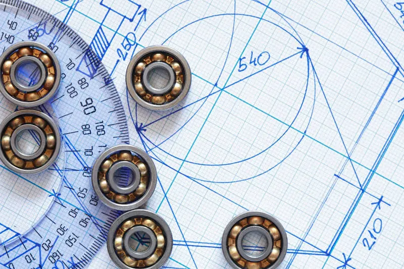
Design choices made early in a project often have the biggest impact on cost and performance.
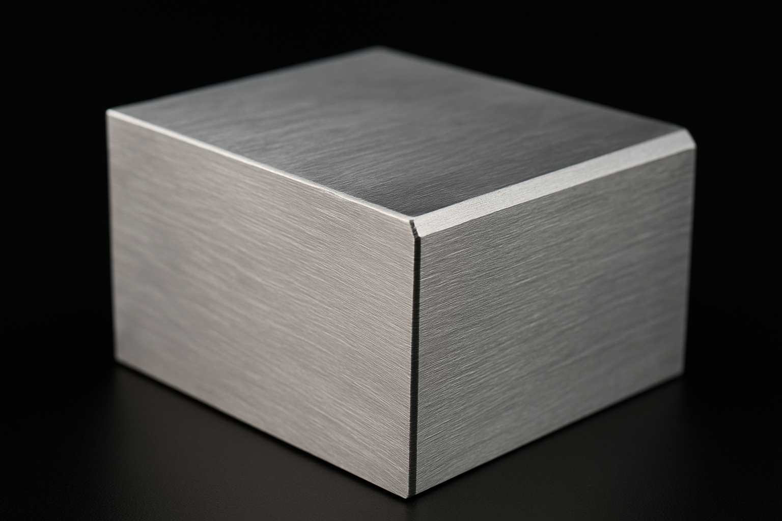
A chamfer is a flat angled edge added to a machined part, usually to remove a sharp corner, help parts assemble, protect exposed edges or improve the finished appearance. In CNC machining, chamfers are small features, but they can affect cost, inspection, fit and long-term performance.
Design choices made early in a project often have the biggest impact on cost and performance. Even small details like a chamfered edge can improve how a part functions, fits, and holds up over time. If you’re sourcing or designing custom machined parts, understanding chamfers is a simple way to improve both quality and efficiency.
In this guide, you’ll learn what a chamfer is, how it differs from fillets, radii and bevels, how to specify chamfer length and angle, and how chamfers affect CNC machining cost, material choice, inspection and repeat production.
Key takeaways
- A chamfer is a flat, angled edge added to a machined part to remove sharp corners, aid assembly, improve handling, protect edges or create a cleaner visual finish.
- The most common chamfer specification is a 45-degree angle, often shown as 0.5 mm x 45° or 1.0 mm x 45°, but the right size depends on the feature’s function.
- Lead-in chamfers are especially useful on holes, shafts, pins, threads and press-fit features because they help parts locate and assemble more smoothly.
- Chamfers are usually quicker and simpler to machine than fillets, but unnecessary chamfers, tight tolerances or inconsistent sizes can still increase CNC machining time and inspection cost.
- For non-critical edges, a general note such as “break all sharp edges” may be enough. For functional edges, specify the chamfer length, angle, tolerance and inspection requirements clearly.
Want a review of your drawing?

What is a Chamfer?
A chamfer is an angled edge that connects two adjoining surfaces, usually cut at around 45 degrees. It's used to remove sharp corners, making parts safer to handle and easier to assemble. In simple terms, the chamfer meaning in manufacturing is all about improving usability and function with a clean, sloped transition.
In practical CNC machining terms, a chamfer is often used on outside edges, hole entrances, threaded holes, shafts, dowel locations, press-fit features, covers, housings and handled components. A chamfer may be purely cosmetic, but it can also be a functional feature that affects assembly, alignment or inspection.
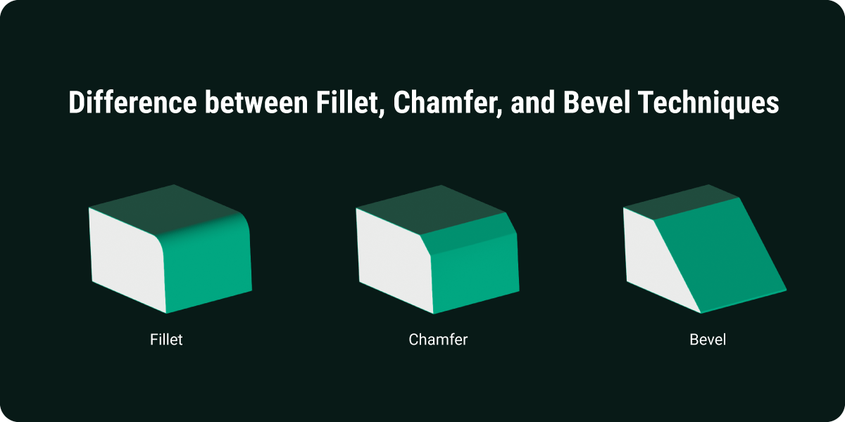
Chamfered vs. Other Edges
Chamfers are commonly compared to fillets, radii, and bevels. A chamfer is a flat angled cut across an edge, often used as a lead-in, edge break or handling feature. A fillet or radius is a curved transition, usually chosen where stress reduction or smoother flow is important. A bevel is also an angled surface, but the term is often used for a larger angled face or edge preparation rather than a small edge break.
Chamfers are ideal for guiding parts into place and reducing the risk of edge damage. Fillets are better for reducing internal stress in parts under load. Bevels are often chosen for aesthetic reasons or where larger angled joints are required.
Angles and Dimensions
Chamfers are most often cut at a 45-degree angle, but they can be adjusted to suit specific part designs. A typical callout might say "1.0mm x 45°," though you can specify length and angle independently depending on your requirements. Keeping chamfer dimensions standard across parts can reduce programming and machining time.
Larger chamfers are useful for parts that need smoother guidance into assemblies. Smaller ones are perfect for simply removing sharp edges without affecting the part's profile. Choose a chamfer size that balances function with ease of production.
For many machined parts, the most cost-effective option is to define functional chamfers clearly and avoid over-specifying every non-critical edge. If a chamfer only removes sharpness for handling, a general break-edge note may be more appropriate than a tightly toleranced callout on every edge.
Tolerances and Specs
Chamfer tolerances are generally more forgiving unless the edge plays a critical role in part alignment or assembly. Specifying tighter tolerances can increase machining time and inspection requirements, which adds unnecessary cost. For non-critical edges, general notes like “Break all edges” often do the job just fine.
When precision is important, be clear about the required depth, angle, and chamfer length. Use measurement tools like chamfer gauges or optical comparators to check dimensions accurately. But where high accuracy isn’t essential, simpler tolerances save time and money.
Before tightening a chamfer tolerance, ask how the chamfer will be measured and what happens if it varies slightly. A chamfer used to start a thread, guide a dowel or locate a mating component may need a defined size and tolerance. A cosmetic edge or general handling edge may not. This distinction helps avoid unnecessary inspection time and prevents non-critical edges from becoming avoidable quality issues.
Functional Uses
Chamfers do much more than remove sharp edges, they improve how parts fit, feel, and perform. Whether you’re working with mechanical assemblies or aesthetic parts, chamfers are a smart design move. In this section, we’ll look at the main functional reasons to include a chamfered edge in your parts.
Lead-in chamfers
A lead-in chamfer is an angled entry feature that helps another part, tool or fastener start smoothly. You will often see lead-in chamfers on holes, tapped holes, shafts, dowel locations, press-fit bores and connectors. They reduce the risk of catching, misalignment or edge damage during assembly.
Lead-in chamfers should be specified more carefully when they control assembly fit. For example, a small chamfer at the start of a tapped hole may help a screw engage cleanly, while a chamfer on a press-fit bore may affect how the mating part starts and seats. If the lead-in is functional, include the chamfer size, angle and any inspection requirements on the drawing.
Assembly Fit
A chamfered edge acts like a lead-in, guiding components into place during assembly. This is especially useful for press fits, dowels, and shaft-and-hole alignments where accuracy matters. It reduces the risk of misalignment or damage, helping parts fit together smoothly.
You'll commonly see chamfers used on bolt holes for faster alignment. They're also added to tube inserts or housings for easier mating. Pin or shaft leads in mechanical assemblies are another frequent use case.
Stress Relief
Sharp internal corners can concentrate stress and may contribute to cracking or fatigue where the part is loaded. A chamfer can remove the sharp corner and improve robustness on some low to moderate load features, but a fillet or radius is usually the better choice where stress concentration is a critical design concern.
Chamfers can be suitable on static or lightly loaded edges where the main goal is to remove a sharp corner, improve handling or aid assembly. For load-bearing transitions, fatigue-sensitive parts or features with high stress concentration, review the geometry carefully and consider a fillet or radius instead.
Safety Benefits
Sharp, unfinished corners can easily cause cuts, snags, or discomfort during handling. A chamfered edge removes this risk and makes the part safer to work with at every stage, from production to installation. This is especially helpful in materials like aluminium and stainless steel, where machined edges can be razor sharp.
You'll often find chamfers on fastener heads to make them easier to grip. They're also used on the edges of housings and covers to prevent injury. Handheld tools and fixtures often rely on chamfers to improve user comfort and safety.
Visual Appeal
Chamfers create sharp, intentional-looking transitions that give parts a clean, high-quality finish. They help surfaces meet in a balanced, symmetric way and can enhance the overall appearance of machined products. Many industries use chamfered edges to signal professional craftsmanship and attention to detail.
They're especially effective when used to create sleek transitions between angled surfaces. Designers also use chamfers to improve the look of exposed corners or part outlines. In branded or polished products, consistent chamfers support a more premium finish.
Materials and Tools
The material you're working with will directly affect how easily a chamfer can be applied. Some materials machine cleanly, while others require more care and specialised tooling. Choosing the right combination of material and chamfering tool ensures a better finish and longer tool life.
Hard Materials
Hard materials like stainless steel and titanium need more robust tools and slower feed rates to achieve clean chamfers. These metals are prone to work hardening, tool wear, and thermal stress if not machined carefully. In stainless steel machining for precision parts, using coated tools and optimised speeds is essential for maintaining accuracy.
Typical challenges include:
- Work hardening during cuts
- Shorter tool life
- Poor surface finish, heat build-up, or premature tool wear if speeds, feeds, and coolant strategy are not controlled
Soft Materials
Materials like aluminium and engineering plastics are easier to chamfer and allow for faster cutting speeds. These softer materials often require less aggressive tooling, making the process more efficient. That's why chamfering is widely used in aluminium machining for CNC components.
Watch for issues like:
- Smearing or gumming in plastics
- Overcutting on soft edges
- Slight deformation at very small chamfer sizes
Chamfer Tools
Most CNC setups use dedicated tools to create chamfers efficiently in a single pass. These tools include chamfer mills, spot drills, and countersinks, each suited to different angles and part types. Choosing the right tool reduces setup time, tool changes, and the risk of inconsistent edges.
Common chamfering tools include:
- Chamfer mills
- Spot drills
- Countersinks
Corners and Internals
External chamfers protect edges from chipping, reduce handling risks, and make parts easier to package. Internal chamfers help components like screws, pins, or connectors align more smoothly during assembly. Both types improve part function and usability without requiring complex design changes.
Useful internal examples:
- Screw starts for blind holes
- Lead-ins on locating pins
- Smooth entry for press-fit components
Cost Considerations
Chamfers usually have a lower cost impact than complex radii or blended surfaces, especially when they use standard angles and can be machined with existing tools. However, chamfers still add cost when they require extra tool changes, secondary setups, tight inspection, unusual angles, difficult access or inconsistent dimensions across the same part.
Simple specs are easier and quicker to produce, while overly complex or tight requirements can drive up machining time and tool wear. In this section, we'll look at what really affects the bottom line when it comes to chamfers.
Volume Impact
When used correctly, chamfers can actually reduce part costs in high-volume production. They streamline assembly, improve fit, and reduce the need for post-processing or touch-ups. This makes them especially efficient when you're using CNC milling services for larger batches.
High-volume advantages include:
- Lower labour per part
- Fewer rejected assemblies
- Easier part packaging and shipping
Design Complexity
Simple chamfers with uniform angles are much faster and cheaper to machine. But if your part includes multi-angled, deep, or inconsistent chamfers, you'll likely face increased programming and machining time. Keeping chamfers consistent in size and angle helps improve inspection speed and process reliability.
Try to avoid issues like calling cosmetic chamfers critical when they don't need to be. Varying angles or depths across different part features also adds unnecessary complexity. A standardised approach to chamfer design usually saves time and reduces risk, provided the chosen size and angle still suit each feature’s function.
Tolerance Costs
Tight chamfer tolerances can slow production and increase tool wear. They may also require additional inspection, which raises overall cost without always improving part performance. Unless the tolerance directly affects function, consider using a general break-edge callout instead.
Some good tolerance practices include:
- Use standard sizes like 0.5mm or 1mm x 45°
- Label critical chamfers separately from cosmetic ones
- Apply looser tolerances on non-functional features
Material vs. Tooling
Material selection plays a big role in chamfering cost, especially when it comes to tool wear and cycle time. To keep costs in check, choose the correct tool coating for wear resistance, avoid specifying tiny chamfers in very hard materials, and combine chamfer passes with other operations where possible. These small adjustments can help maintain edge quality while keeping production efficient and budget-friendly.
We're ready to help you with your project.

Designing Chamfers for Performance and Efficiency
Designing effective chamfers starts with understanding their purpose. Whether you're breaking edges for safety, guiding parts into position, or improving a component's visual quality, knowing the goal helps shape the right approach. Once that's clear, you can choose the simplest and most cost-effective chamfer that meets your requirements.
Smart chamfer design includes using standard angles like 45° to reduce tool changes, avoiding overly tight tolerances unless necessary, and including chamfers early in the CAD model. These small decisions improve machinability, reduce production time, and help avoid last-minute design changes. By planning chamfers from the start, you save time, reduce waste, and produce more reliable parts across every batch.
Chamfer design checklist before you request a quote
Before sending a CNC machining drawing for quote, review each chamfer and decide whether it is functional, cosmetic or simply an edge break. This helps your machining supplier quote accurately and prevents unnecessary cost from being built into non-critical features.
- Mark functional chamfers separately from cosmetic chamfers.
- Use 45-degree chamfers where the design allows.
- Keep repeated chamfers consistent in size and angle.
- Use a general break-edge note for non-critical sharp edges.
- Define the size, angle and tolerance where the chamfer affects fit, assembly or inspection.
- Check whether internal chamfers are accessible with standard tooling.
- Confirm whether finishing, anodising, passivation or bead blasting will affect the final edge condition.
- Agree inspection requirements for critical chamfers before production.